Honeywell FCE
The Honeywell FCE specification defines the necessary and optional features for a Point-to-Point Data Bus Protocol for deployment in several applications within the Boeing 787 Flight Control Electronics (FCE) System.
The HFCE VIs allow programming of MAX Technologies' devices supporting the Honeywell FCE Direct Mode Rate Sensors (DMRS) Buses. The FCE DMRS Buses are dedicated broadcast 400 kbit/second links from the sensor package to system ACEs.
HFCE Terminology
| Terms | Meaning |
|---|---|
| HFCE | Honeywell Flight Control Electronics protocol |
| DMRS | Direct Mode Rate Sensors (DMRS) are one of the three bus types describe in by Honeywell FCE protocol. |
| Word | HFCE word is 16-bit long. Depending on its position, a word can code for a label, a length or a data word. Word composes messages. |
| Message | In a VI, a DMRS message is composed of three 16-bit words. label word, data-length word and 0 to 62 data words. |
| Packet | In a VI, a DMRS packet is composed of the Message words plus the CRC word. |
| Label | A DMRS label is a word that identifies the message. |
| Payload size | The payload size is a word sent to tell the number of data words coming next. |
| Payload | The payload is the useful data carried in each messages. The payload is composed of 0 to 62 data words. |
| CRC | Each message has a verification word called Frame Check Sequence (FCS). FCS is implemented using a cyclic redundancy check (CRC) 16-bit word. |
Message packet
The HFCE message consists of the following packet-based construction
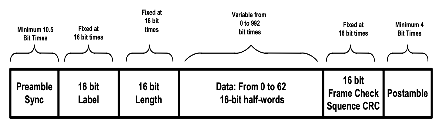
- Up to 62, 16-bit words per packet
- Unique label for each packet
- Embedded length field (payload size)
- 16-bit CRC check
Encoding
The HFCE message at physical layer is encoded using Manchester encoding for synchronous receiver clock recovery
Databus electrical
The HFCE Databus electrical key features are:
- Transformer-coupled Physical Layer using RS-485/422 class transceivers
- Works into twisted shielded pair (twinax) cabling
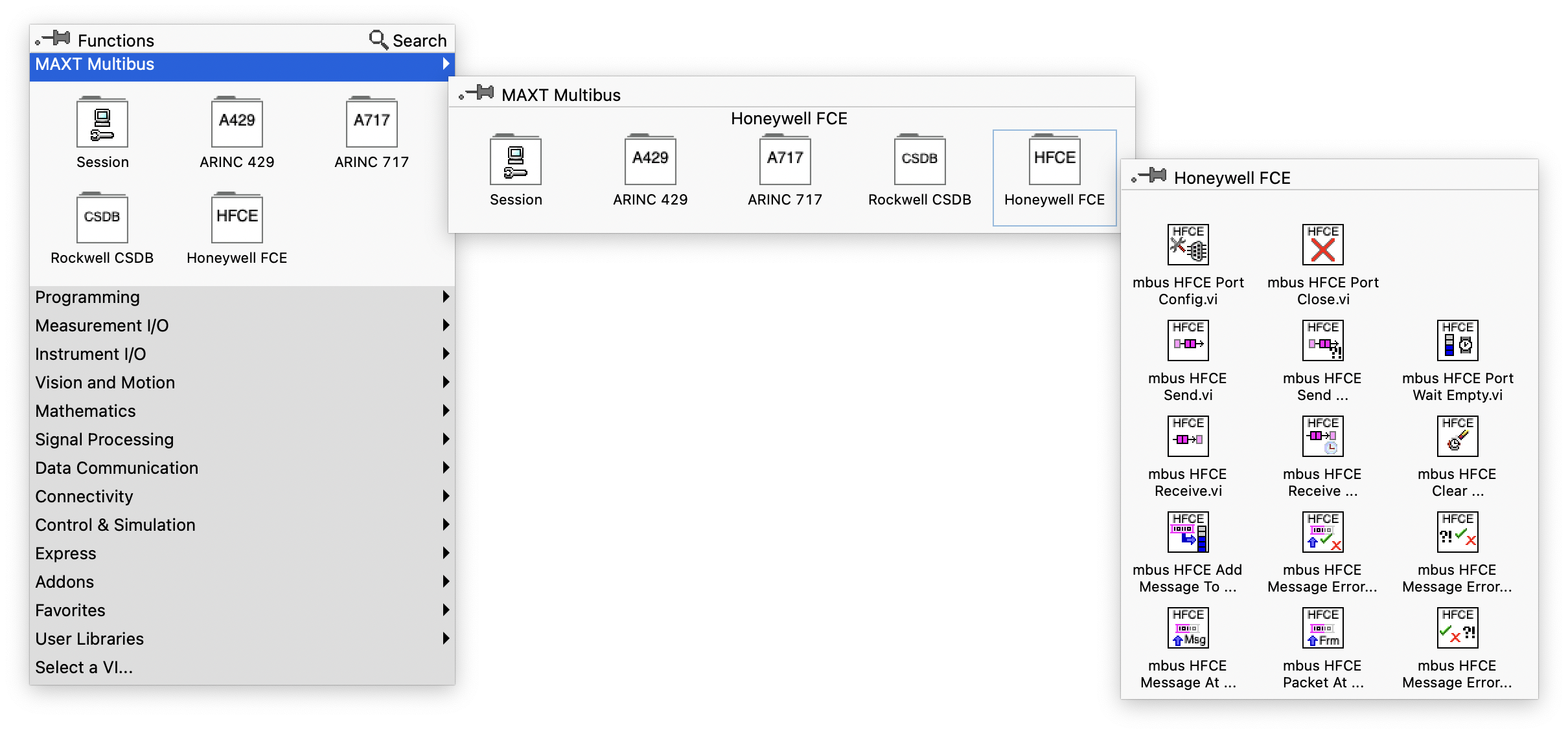
VI Palette
The provided VI (function) palette allows HFCE port configuration, sending and receiving HFCE messages, manipulating HFCE messages and closing HFCE ports.
Usage
LabVIEW HFCE based application must include VIs to create and terminate a Multibus session.
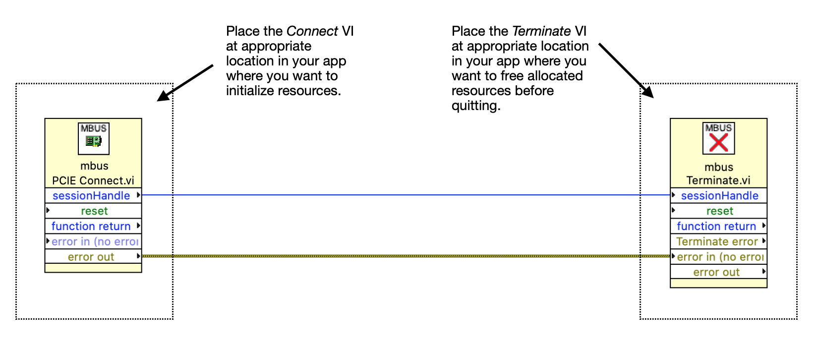
In the LabVIEW HFCE application, the appropriate Connect VI (mbus PCIE Connect.vi for a PCI Express or PXI Express connection) is placed in the app initialization.To end with a session, mbus Terminate.vi must be placed to clean up tasks and terminate the session properly.
A session is created with the Connect VI and is maintained up to mbus Terminate.vi. A sessionHandle identifies the created session. The next step is to configure the HFCE port.
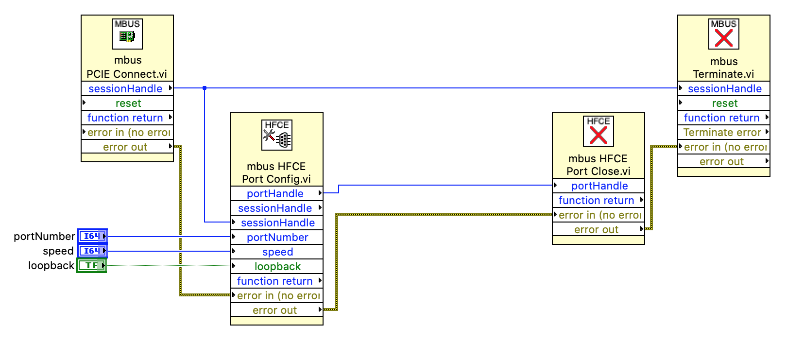 The mbus HFCE Port Config.vi configures the HFCE port. The VI must be placed at the appropriate location, and in any case, after the Connect VI. The sessionHandle returned by the Connect VI must be wired to mbus HFCE Port Config.vi. The mbus HFCE Port Config.vi returns a portHandle that uniquely identifies this HFCE port.
The mbus HFCE Port Close.vi should be placed at the appropriate location to finish using the HFCE port. It must be wired to the portHandle.
If multiple HFCE ports are available on the hardware, the port number must be used to select desired port. Default port number is 0. The HFCE port is configured with a bus speed (default is 400,000 bps) and a loopback (default is false).
Once the HFCE port is configured, the port is activated and will buffer any received data from the physical bus if the loopback is set to false. If the loopback parameter is set to true, the port is configured to buffer received data from the port transmitter internally. In the context of a self test, the loopback parameter must be set to true. No hardware interface is needed.
Those four VIs form the basic HFCE LabVIEW app data flow. The next step is to add the HFCE VIs to send or receive DMRS messages.
To read incoming HFCE databus messages, Multibus VI offers two Receive VIs: mbus HFCE Receive.vi and mbus HFCE Receive Advanced.vi. They both read received DMRS messages. Advanced receiving comes with more parameters to read time tags and errors. They must be wired to the HFCE Config Port VI already placed.
To send HFCE databus messages, Multibus VI offers two Send VIs: mbus HFCE Send.vi and mbus HFCE Send Advanced.vi. They both send DMRS messages. Advanced sending comes with more parameters allowing errors injection. They must be wired to the HFCE Config Port VI already placed.
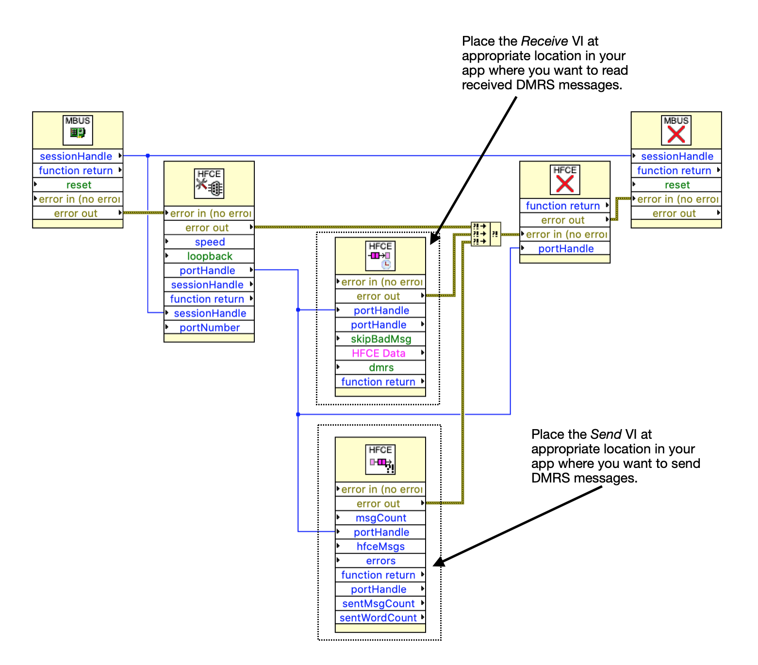
The above figure shows basic wiring for a single read of received HFCE messages. For continuous reading, mbus HFCE Receive.vi or mbus HFCE Receive Advanced.vi must be included into a loop. The messages are populated in the hfceMsgs buffer. The hfceMsgs buffer is an array of 16-bit words.
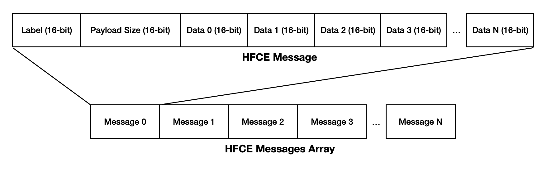
The hfceMsgs buffer is built as above. Example below shows a hfceMsgs with two messages with labels AA and BB and of respective payload sizes of 3 and 4 words.
| hfceMsgs index # | 16-bit word |
|---|---|
| Index #0 | 0x00AA (first message label) |
| Index #1 | 0x0003 (payload size) |
| Index #2 | 0x0011 (data 0) |
| Index #3 | 0x0022 (data 1) |
| Index #4 | 0x0033 (data 3) |
| Index #5 | 0x00BB (second message label) |
| Index #6 | 0x0004 (payload size) |
| Index #7 | 0x1100 (data 0) |
| Index #8 | 0x2200 (data 1) |
| Index #9 | 0x3300 (data 3) |
| Index #10 | 0x4400 (data 4) |
The skipBadMsgs and DMRS input parameters relates to DMRS message errors. The mbus HFCE Receive.vi always returns only good received messages to the user. By default, mbus HFCE Receive Advanced.vi returns all received messages to the user. By setting skipBadMsgs to true, any messages with at least one error is discarded. With SkipBadMsgs at true, the user is sure to see valid messages only. Each receive VI displays the number of messages in error by reading the errorCount output parameter.
If the user works on a Honeywell FCE Direct Mode Rate Sensors (DMRS) Bus, the DMRS input must be set to true. DMRS buses do not consider messages with odd lengths as erroneous. With DMRS at true, Multibus VI does not return errors when messages are of odd lengths.
The msgCount output parameter indicates the number of HFCE messages contained in the hfceMsgs array. The wordCount output parameter indicates the number of 16-bit words contained in the hfceMsgs array.
Overflow error
Continuously reading received data must be done at a pace to avoid receive buffer overflow. Overflow errors are reported by the mbus HFCE Receive Advanced.vi when the incoming new data overwrites the data already in the buffer and waiting to be read. In such situation, the new data overwrites the unread ones resulting in data loss. Application must be designed to allow sufficient receive buffer size and do repeated calls to the mbus HFCE Receive Advanced.vi within short delay to avoid buffer overflow.
Overflow error can be handled by calling the mbus HFCE Clear Overflow.vi once the error occurred. Clearing the overflow error allows to continue reading the received data using mbus HFCE Receive Advanced.vi.
Message error
When reading received data using the mbus HFCE Receive Advanced.vi , the output parameter errorCount indicates the number of messages received with errors within the hfceMsgs buffer array.
When the errorCount output parameter value is zero, all the messages contained in the hfceMsgs buffer array are considered valid without errors.
When the errorCount value is not zero, one or more messages contained in the hfceMsgs buffer array are erroneous. The errorCount value reflects how many messages are flagged as erroneous. The erroneous message(s) can be identified using the message error informations contained in the errors output parameter.
The errors output parameter is and array of 64-bit values where each value contain packet CRC value and error information for each received HFCE message.
Each received HFCE message is time stamped with a 64-bit value at nanosecond resolution. Message timetag is stored in the timetags output array parameter. The timetags output parameter is an array of 64-bit values where each value is the time tag in nanosecond for each received HFCE message.
This concludes the basics of creating a Multibus Session, configuring an HFCE Port and reading incoming HFCE messages.