Getting Started
Multibus VI offers function sets used to manage a Multibus session and send / receive messages on supported databuses. This chapter covers the basics to get you started.
General Terminology
| Terms | Meaning |
|---|---|
| Device | MAX Technologies databus product. Supported devices include MAX Technologies Flex family of instruments and PCI Express / PXI Express cards. |
| Session | A Multibus session is created when a user connect to a supported device. It ends when the user disconnect of the device. |
| Port | A Multibus port is the communication endpoint. Generally, endpoints have transmit and receive capabilities. |
| MULTI Port | Available on some devices, the MULTI ports allow selecting the databus protocol associated with each port. A MULTI port supports any protocol from a list of available protocols. |
| Serial Port | Available on some devices, the Serial ports can be used as Serial Async or CSDB protocol. |
| Handle | Multibus handle is a reference to Multibus resources such as session and port. |
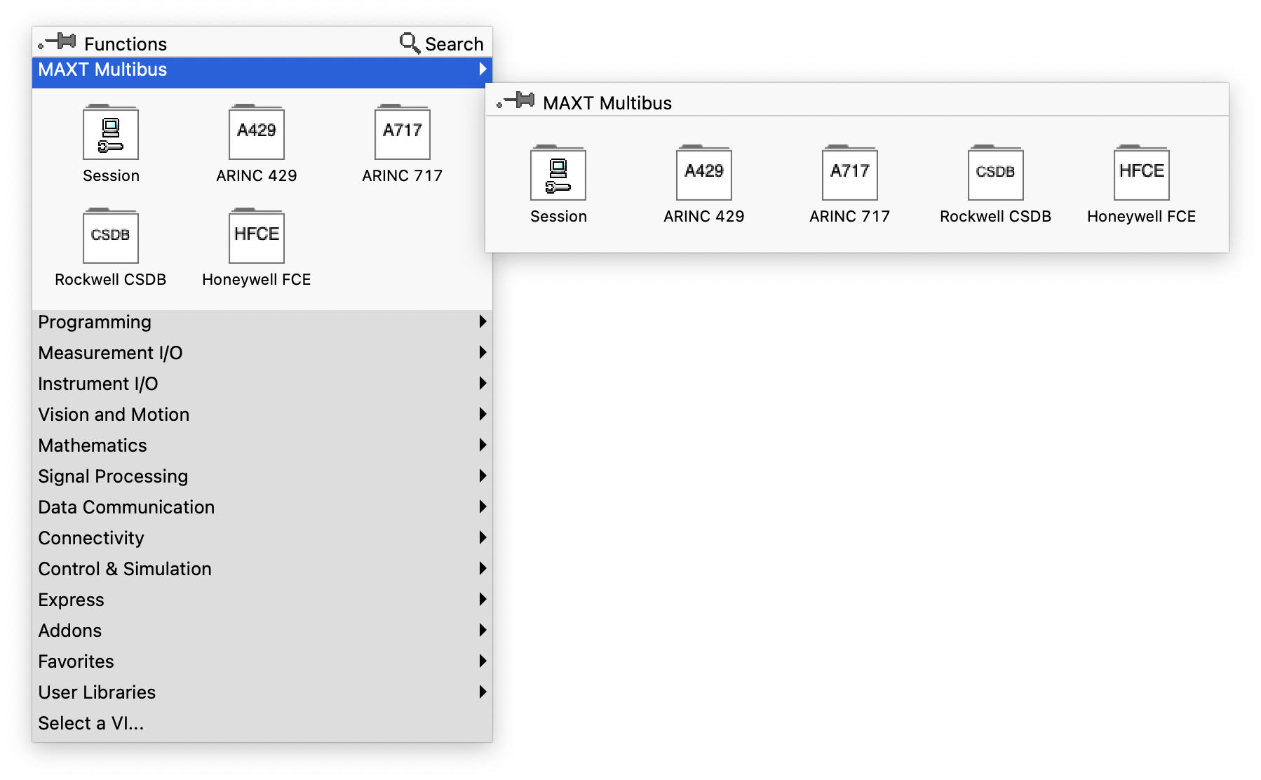
Multibus VIs Palettes
Multibus VI offers a separate palette set for each protocol, plus an additional palette set called Session.
-
Session palette: this palette encloses all functions that are not specific to any protocols. For example: connect to a device using USB, Ethernet or PCI Express, manage device configuration, inquire supported databus protocols on a device and more. LabVIEW Multibus app must always call Session functions to create and terminate a session.
-
Databus protocol specific palettes: each of these palettes encloses all functions that relate to a specific protocol. For example: configure a databus port, setup databus communication speed, setup output voltage, send and receive data.
Multibus VI currently supports the following databus protocols:
- ARINC 429
- ARINC 717
- Honeywell FCE
Databus send and receive
Sending and receiving databus data is vastly simplified when using Multibus VI. Once a port is configured using the Port Config function, this port is ready to send and read received data. Sending and receiving are controlled using relevant functions on the protocol specific palettes.
Queuing
Sending and receiving can be done using queuing functions to buffer messages.
When sending messages, the user fills a buffer with messages to transmit and the device will send the buffer sequentially until buffer is empty.
The receiver sequentially buffers all received messages from a port. The device's onboard processor stores all the messages as it is received with precise time stamping. The user sequentially reads the receive message buffer.
Queuing mode is available on all supported databus protocols.
Sampling
Sampling functions are used to send and receive messages repetitively based on specific message address or label at a programmed period.
Sampling mode is useful to send databus messages based on their address or label at a given period interval. The user simply has to specify the address or label, data and the desired message period. The device scheduler sends each of the programmed messages at their specific programmed period.
Once a schedule is running on a device, each address or label message is sent at its specified interval without user intervention. The last programmed message for a given address or label is sent repetitively at the programmed interval. Update function is available to update a message data for a specific address or label while the scheduler is running.
Sampling mode receivers store the messages on the device memory based on their address or label. The sampling logic keeps the last received message for a corresponding address or label. Sampling functions are available to read the received address or label messages and their corresponding periods.
Sampling mode is available on databus protocols supporting address or label based periodic messages scheduling like ARINC 429, ARINC 629, CAN, CSDB and others.
Timing management
MAX Technologies has implemented highly accurate timing management onto all hardware. All transmit and receive message are time stamped using a 64-bit nanosecond tag.
Execution Error Handling
All Multibus VI functions return a success or error code. It is highly recommended to always connect the error in and error out function nodes. Error code can be decoded to English using the mbus Error String.vi function.
I/O Error Handling
All supported databus protocols allow error injection when sending messages and message error status detection when receiving. These I/O errors are available with the Advanced Send and Receive VIs.